Starting from the Workstation: Practical Guidelines for Jib Cranes
When it comes to choosing a jib crane, the biggest fear is flipping through a parameter table without knowing where to begin. The actual conditions at the workstation—whether the floor can be excavated, whether a column can support mounting, how heavy the workpiece is, how many lifts are performed per day—these are the first thresholds that determine whether the equipment can be installed and whether it will be easy to use. Parameters are the result, not the starting point.
Below, following the order of on-site decision-making, we break down a selection logic that works backward from workstation conditions to equipment configuration.
First look at "where to hang it," then discuss "how much to lift"
The installation form of a jib crane is constrained by the building conditions around the workstation, rather than selecting a model first and then modifying the factory building. Reversing this order often incurs additional civil engineering costs.
If the workstation is located in the middle of the workshop, the floor is a concrete slab, and conditions allow for excavation and pouring, a free-standing column-mounted type is the most conventional choice. It comes with its own column, and the slewing angle can reach 270° to 360°, covering a complete circular or sector-shaped work area. However, the prerequisite is that the floor bearing capacity must be verified. Light-duty equipment generally requires a floor bearing capacity of no less than 2 tons per square meter, and the floor thickness should not be less than 150 mm; if the lifting capacity rises to 2 to 3 tons, the floor bearing capacity requirement increases to about 4.5 tons per square meter, the thickness must also reach 250 mm, and the foundation or surrounding beams and columns often need reinforcement. Many old factory floors were not originally designed to account for the dynamic impact loads of lifting equipment, and directly fixing the column with expansion bolts carries risks. Structural review before installation is not optional.
If the workstation is close to a load-bearing column or solid wall, and floor space is tight and forklift passages cannot be occupied, a wall-mounted type is a more practical choice. It mounts directly onto the factory's original load-bearing structure, does not touch the floor, does not occupy space, and the slewing range is typically between 180° and 270°. However, the hard constraint here lies in the load-bearing capacity of the wall or steel column.
Non-load-bearing walls cannot be considered. Even for concrete columns or steel columns, it is necessary to confirm whether their design load has a reserved margin for suspended equipment. Another practical issue with wall-adjacent workstations is interference from pipes and cable trays—if an air duct or cable tray crosses the slewing path of the jib, even a large slewing angle is meaningless. For situations where floor damage is not allowed, or where the equipment needs to be shared across workstations in turn, a mobile jib crane provides a compromise. It maintains stability through base counterweight, has casters for pushing, and eliminates foundation construction. The cost is that lifting capacity is generally limited, mostly within 2 tons, and the casters must be locked during operation; it cannot travel long distances with a load. It is suitable for maintenance, temporary lifting, or auxiliary workstations with low cycle rates, and is not suitable as the core lifting equipment of a fixed production line.
Workpiece and frequency determine "boom length" and "duty class"
Once the installation conditions are determined, the next step is to answer two directly related questions: how far the jib needs to extend, and how frequently the equipment must endure use.
The jib length is not better the longer it is. The longer the boom, the greater the bending moment borne by the boom root under the same lifting capacity, and the required cross-sectional dimensions and overall self-weight will increase. More critically, the effective working radius is often overestimated—machine tools, material racks, and pipes around the workstation may all intrude, and the actually usable slewing sector area may be considerably smaller than the theoretical radius. A reasonable approach is to determine the boom length based on the horizontal distance from the farthest lifting point to the center of the column, leaving a moderate margin. Excessive margin instead brings operational inconvenience and cost waste.
Regarding lifting capacity, it is necessary to distinguish between "rated lifting capacity" and "actual commonly used load." Jib cranes belong to light-duty working-intensity cranes, designed to serve short-distance, high-frequency workstation lifting, rather than replacing bridge cranes for heavy-load transport. If 90% of the lifting tasks at a workstation involve loads below 500 kg, but the equipment is configured for 3 tons, not only is the procurement cost high, but daily operational efficiency may actually decrease because the equipment is bulky and has poor fine-control performance.
What is more easily overlooked than tonnage is the duty class. The duty class of a jib crane is divided into A1 to A8: light duty corresponds to A1 to A4, medium duty corresponds to A5 to A6, and heavy duty corresponds to A7 and above. This class reflects the busyness of the hoisting mechanism per unit time, rather than simply how heavy the load is. A 200 kg workpiece lifted 300 times per day may place far higher demands on equipment fatigue life than a 1-ton workpiece lifted 10 times per day. If the workstation has a tight cycle and intensive lifting movements, the duty class should be shifted up one level during selection; otherwise, the wear rate of components such as slewing bearings and hoist brakes will exceed expectations.
Working environment determines "what material, what protection"
With the same lifting capacity and boom length, equipment life may differ several times over in different workshop environments. The cost of selection errors in this part often only becomes apparent six months to a year after installation, but the correction cost is very high.
The environmental characteristics of machining workshops include cutting fluid splash, chip accumulation, and oil mist. For ordinary carbon steel equipment in this environment, slewing bearings and electric hoist brakes are weak points. Once dust and oil contamination enter the slewing mechanism, manual slewing becomes sluggish, and the motor load of electric slewing also increases. For such workstations, it is recommended to use hoisting motors with a protection rating of not less than IP54, slewing bearings with dust-proof sealing structures, and boom surfaces treated with epoxy paint or hot-dip galvanizing to resist cutting fluid corrosion.
The core threats at welding workstations are welding spatter and high temperature. Welding spatter falling onto the hoist chain or wire rope directly damages load-bearing components; high-temperature radiation accelerates motor insulation aging. An experienced configuration approach is to add high-temperature-resistant protective sleeves to the chain or wire rope, add stainless steel protective covers to the motor and electrical control parts, and arrange power components away from directly above the welding point. In such situations, an articulated boom structure is sometimes more advantageous than a straight boom, because the two hinged boom sections can adjust posture to bypass welding fixtures and fume hoods, delivering the hook to positions a straight boom cannot reach.
The selection logic for clean or corrosive environments is different again. Workshops such as pharmaceuticals, electronics, and food processing are sensitive to metal chips and particulate matter. Peeling paint or grease leakage from bearings on ordinary carbon steel equipment may constitute a contamination source. What such workstations require is not just material upgrading, but the structural treatment approach of the entire machine—stainless steel booms, concealed wiring, non-shedding design—configured according to cleanroom usage specifications. Chemical or electroplating environments must additionally consider the corrosion of acid mist and salt spray on electrical components. Explosion-proof or corrosion-proof configuration must run through the entire electrical chain of the hoist, motor, and control box. Replacing only the hoist with an explosion-proof one while the controller remains ordinary is equivalent to not having done explosion-proof work at all.
Operating experience is the final verification step
The people who use the equipment every day after installation often judge selection quality more accurately than a parameter table. Whether slewing is light and smooth, whether positioning is easy, whether the hoist runs smoothly—these things at the "feel" level actually correspond to several hard indicators.
For manually slewed jib cranes, slewing resistance torque comes from bearing friction and eccentric load due to boom self-weight. In a well-designed slewing mechanism, an operator can push a fully loaded boom with one finger. Behind this is the combined result of bearing selection and installation precision. If slewing is laborious and feels jerky, it indicates either that the bearing selection is too small or that the verticality installation deviation of the column is too large.
For assembly workstations that require frequent fine adjustment and positioning, the speed regulation performance of the electric hoist deserves more attention than the rated lifting capacity. The lifting speed of ordinary chain hoists is usually fixed at two speeds or a single speed, with an obvious impact during start and stop. Precision assembly scenarios are better suited to hoisting mechanisms equipped with variable-frequency speed regulation or servo drive; start-stop acceleration can be controlled at a low level, and the hook can achieve millimeter-level inching positioning. The extra budget spent here buys a reduction in workpiece collision risk and a decrease in operator fatigue.
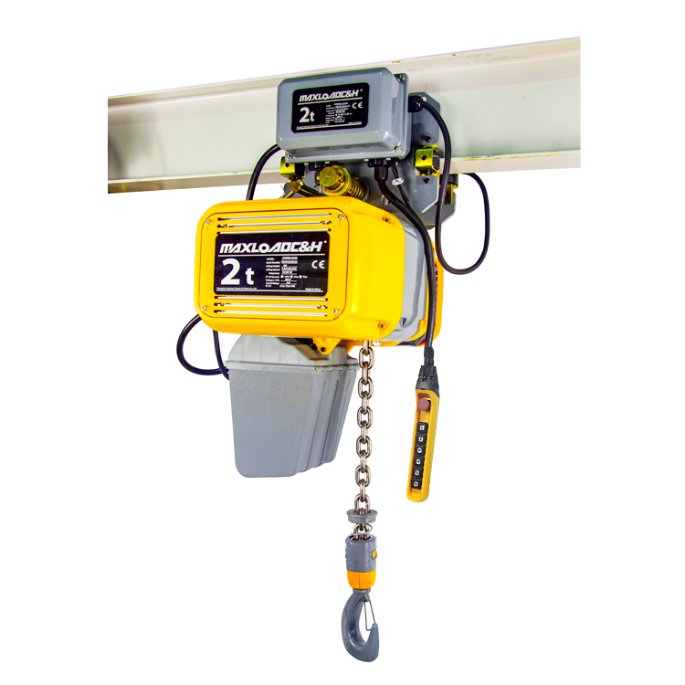
Another detail easily overlooked on site is the operation method. A pendant control handle or wireless remote control may seem like a small issue, but it actually affects workstation layout. The cable of a pendant control handle needs to be dragged as the jib slews. If the workstation has moving parts or passages around it, the presence of the cable itself is a hazard. Wireless remote control eliminates cable constraints, but during selection it is necessary to confirm whether control signal stability and battery life match the workshop's electromagnetic environment and shift duration.
Self-check list before implementation
Before determining the final configuration, several basic data items should be checked one by one: the actual load-bearing conditions of the workstation floor or wall/column, with structural professionals providing verification opinions when necessary; the maximum external dimensions and center-of-gravity position of the lifted object, which relate to hook type and clearance requirements; whether there are pipes or cable trays above the workstation limiting the slewing height of the jib; and the power supply access point and control method. With this information in hand, when communicating parameters with the supplier, selection deviation will be much smaller.
A jib crane is not general-purpose equipment; it is a local lifting tool customized for a specific workstation. Putting workstation conditions first in the selection logic gives the remaining decisions a natural basis.
 0086 156 1824 5535
 0086 156 1824 5535
 kimliu@chnhoist.com